

close
Choose Your Site
Global
Social Media
Views: 0 Author: Site Editor Publish Time: 2026-09-30 Origin: Site


Mismatched separation equipment in clinical and research labs creates hidden operational bottlenecks that quietly degrade daily throughput. When you experience sample degradation or compromised pellet integrity forces your technicians to repeat tedious washing steps, the root cause usually traces back to inadequate centrifugation parameters. Procuring the correct separation platform is rarely a simple matter of matching a basic RPM requirement. You must align Relative Centrifugal Force (RCF), rotor versatility, process fluid properties, and scalable capacity with strict assay requirements and safety compliance mandates.
Relying solely on revolutions per minute as a performance metric creates significant processing risks. You need a rigorous, technical framework for evaluating equipment specifications before finalizing any procurement decision. This guide details how to assess rotor configurations, match mechanical capabilities to specific fluid dynamics, and mitigate adoption risks when integrating new separation technology into your existing laboratory workflows.
RCF Supersedes RPM: Procurement decisions must be based on g-force capabilities (RCF) tailored to specific protocols, as RPM is a relative metric dependent on rotor radius.
Rotor Versatility Dictates Lifecycle Value: The choice between swing-out (horizontal/basket-type) and fixed-angle rotors directly determines throughput efficiency, pellet formation, and sample integrity.
Fluid Properties and Spin Profiles Matter: Sample density, viscosity, and fragility require programmable acceleration and deceleration profiles to prevent resuspension.
Capacity Scaling Prevents Obsolescence: Evaluating current microplate and tube volumes against projected future throughput needs is critical to avoiding premature equipment replacement.
Compliance and Safety are Non-Negotiable: Prioritize units featuring aerosol-tight biocontainment, automated imbalance detection, and intuitive protocol locking to mitigate risks when handling biohazardous materials.
Many lab technicians operate under the assumption that rotational speed dictates separation power. This leads to the flawed strategy of searching for a generic 3000 rpm centrifuge without factoring in the physical dimensions of the rotor. Revolutions per minute (RPM) only measures how fast the rotor spins around its axis. Relative Centrifugal Force (RCF), expressed as multiples of the Earth's gravitational field (x g), measures the actual force exerted on your sample.
The relationship between these two metrics depends entirely on the rotor's radius. The formula for calculating RCF is RCF = 1.118 × r × (RPM/1000)², where 'r' represents the radius in millimeters. A rotor with a 100 mm radius spinning at 3000 RPM generates significantly less g-force than a rotor with a 200 mm radius spinning at the exact same speed. Standardizing protocols across different laboratory sites requires communicating strictly in RCF. If a protocol specifies RPM without defining the rotor radius, reproducibility becomes impossible. You will see inconsistent pelleting and variable sample yields.
Let's look at a practical lab scenario. You have two centrifuges from different manufacturers. Centrifuge A has a fixed-angle rotor with a 150 mm radius. Centrifuge B has a swing-out rotor with a 220 mm radius. If you set both machines to 3000 RPM, Centrifuge A generates roughly 1500 x g. Centrifuge B generates nearly 2200 x g. That 700 x g difference will completely alter your cell pelleting results. Cells might shear in Centrifuge B while remaining perfectly intact in Centrifuge A. Always audit your Standard Operating Procedures (SOPs) to ensure they list RCF, not RPM.
The physical characteristics of your process fluid heavily influence the required separation parameters. Viscosity, density, and particle size dictate both the necessary RCF and the total spin duration. High-viscosity fluids resist the movement of particles. You will need either a higher g-force or an extended spin time to achieve complete sedimentation. Conversely, separating particles in a low-viscosity buffer happens rapidly. You need precise control to avoid over-compacting the pellet.
Matching the mechanical capabilities of a low speed laboratory centrifuge to these fluid characteristics ensures optimal separation without inflicting excessive mechanical stress on delicate samples. For density gradient separations, such as isolating peripheral blood mononuclear cells (PBMCs) using Ficoll, the fluid density layers must remain undisturbed. This requires highly controlled, gradual acceleration and braking phases. Ignoring these fluid dynamics often results in mixed layers, sheared cells, or resuspended pellets.
Consider the difference between spinning down a standard aqueous buffer versus a heavy glycerol solution. The glycerol solution exerts massive drag on suspended proteins or cellular debris. If you apply standard spin parameters designed for water-based buffers, you will pull the tubes out and find the debris still suspended in the supernatant. You must adjust the run time to compensate for the fluid's resistance.
Different scientific disciplines demand distinct performance criteria from their separation equipment. Understanding these specific requirements prevents you from deploying inadequate hardware.
Clinical Diagnostics: The primary requirement involves blood component fractionation. The equipment must yield clear separations of serum, plasma, and the buffy coat without causing hemolysis. Smooth acceleration profiles are mandatory to protect fragile erythrocytes from rupturing during the initial spin phase.
Life Sciences: Protocols frequently require gentle cell culture pelleting, washing steps, and the sedimentation of bacteria or other microorganisms. Success depends on forming a cohesive but easily resuspendable pellet. Excessive force damages cell membranes, reducing viability for downstream culturing or analysis.
High-Throughput Screening: Laboratories processing large volumes of assays require seamless integration for washing and spinning down samples. This often necessitates a dedicated microplate centrifuge setup capable of handling multiple plate formats simultaneously without causing cross-contamination or well spillage.
Application | Typical RCF Range (x g) | Key Success Metric |
|---|---|---|
Mammalian Cell Pelleting | 200 - 500 | High cell viability, soft pellet formation |
Blood Fractionation (Plasma/Serum) | 1,500 - 2,000 | Zero hemolysis, distinct buffy coat layer |
Bacterial Cell Harvesting | 3,000 - 5,000 | Firm pellet, clear supernatant |
Density Gradient (PBMC Isolation) | 400 - 800 | Intact gradient layers, no mixing during deceleration |
Swing-out rotors utilize buckets or baskets attached to a central yoke via hinge pins. At rest, the tubes hang vertically. As the rotor accelerates, centrifugal force causes the buckets to swing outward, transitioning the tubes to a strict 90-degree horizontal angle during operation. This mechanical design ensures that particles sediment directly along the center axis of the tube, accumulating at the very bottom.
This configuration excels at achieving flat pellet formation and is the standard for delicate density gradient separations. Floor-standing models equipped with large swing-out rotors accommodate massive capacities, sometimes processing up to 6 liters per run. However, the design introduces specific trade-offs. The swinging buckets create significant aerodynamic friction, which limits the maximum achievable speeds compared to rigid designs. The increased drag also generates more heat, which can impact temperature-sensitive samples during prolonged runs.
When you load a swing-out rotor, you must pay strict attention to bucket pairing and weight distribution. The hinge pins bear the entire load of the bucket and sample under extreme g-force. If you fail to lubricate these pins regularly, the buckets will not swing freely to the full 90-degree position. This causes severe vibration, poor pellet formation, and eventual mechanical failure of the rotor yoke.
Fixed-angle rotors hold sample tubes in rigid cavities machined directly into the rotor body, typically at angles ranging between 25 and 45 degrees. Because the tubes remain stationary relative to the rotor axis, the particles travel outward radially but strike the side wall of the tube before sliding down to the base.
This aerodynamic, compact design allows for faster rotational speeds and quicker pelleting of robust particles. It maintains a smaller equipment footprint, making it ideal for crowded benchtops. The primary trade-off involves the pellet geometry. Fixed-angle rotors produce angled pellets smeared along the lower side wall of the tube. This angled accumulation complicates supernatant decanting, increasing the risk of accidentally dislodging the pellet. Additionally, these rotors generally offer limited volume capacity per tube compared to high-capacity swing-out alternatives.
If your workflow involves decanting supernatant by simply inverting the tube, an angled pellet poses a high risk of sample loss. The pellet can easily slide down the tube wall and into your waste container. You often have to use a pipette to carefully draw off the liquid, which adds time to high-throughput workflows.
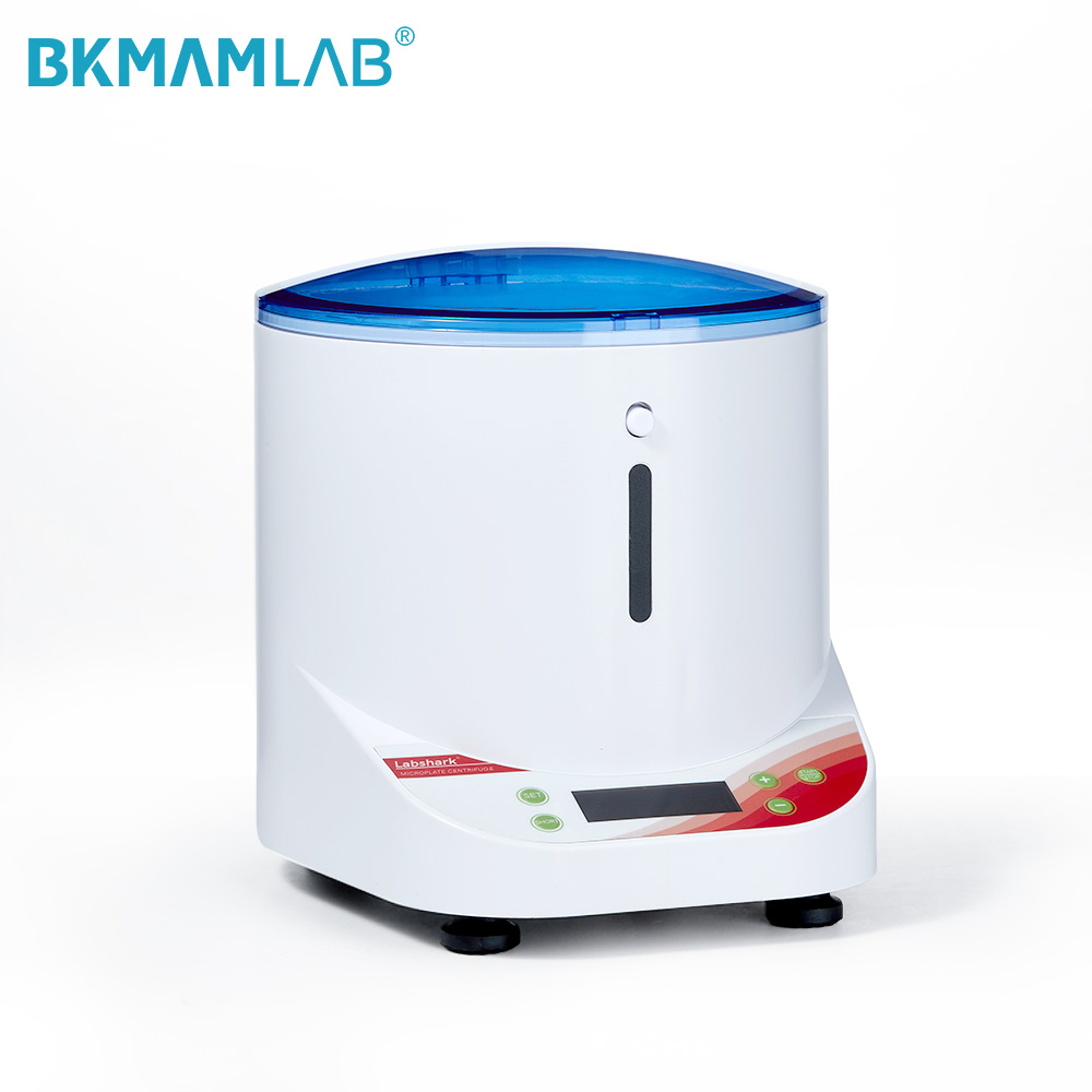
High-throughput genomics and proteomics workflows rely heavily on standardized microplates. Processing these formats requires specialized carriers designed to support the fragile plastic architecture of the plates under high g-forces. When evaluating a plate centrifuge, compatibility with deep-well plates, standard 96-well microplates, and skirted or unskirted PCR plates is paramount.
Throughput and balancing considerations dominate high-volume ELISA and genomic workflows. Plate rotors must provide exact horizontal positioning to prevent liquids from creeping up the well walls and causing cross-contamination. Furthermore, the carriers must be perfectly balanced. Even minor discrepancies in plate weight, like a fully loaded deep-well plate versus a partially filled one, can trigger imbalance sensors and halt the protocol.
You must also verify the maximum height clearance of the plate carriers. Many standard carriers only accommodate a single standard-height microplate. If your protocol requires stacking a filter plate on top of a collection plate, you need deep carriers specifically designed for that extended height. Failing to check this specification means you cannot close the centrifuge lid or the plates will jam against the rotor chamber during the spin.
Rotor Type | Primary Mechanism | Optimal Applications | Main Limitations |
|---|---|---|---|
Swing-Out | Tubes transition to 90-degree horizontal angle during spin. | Density gradients, blood fractionation, flat pelleting. | Lower maximum speeds, higher aerodynamic drag, requires pin lubrication. |
Fixed-Angle | Tubes held rigidly at 25-45 degree angles. | Rapid pelleting of robust particles, compact footprint. | Angled pellet formation, harder to decant supernatant, lower volume per tube. |
Microplate Carriers | Horizontal baskets designed for standardized plate footprints. | ELISA washing, PCR spin-downs, high-throughput assays. | Strict balancing requirements, limited to specific plate heights, lower max RCF. |
Balancing physical space constraints against required processing volume dictates the choice between benchtop and floor-standing models. Benchtop units conserve valuable floor space but generally max out at around 3 to 4 liters of total capacity. Floor-standing models consume dedicated square footage but offer superior ergonomics for loading heavy rotors and processing up to 6 liters simultaneously.
Beyond the base unit, assess the adapter ecosystem. A robust separation platform relies on a comprehensive range of adapters that allow a single rotor to accommodate various tube sizes. Evaluate the availability and structural integrity of adapters required to switch seamlessly between 1.5mL microtubes, 50mL conical tubes, and standard blood collection tubes. A limited adapter selection forces laboratories to purchase multiple rotors, inflating capital expenditure and complicating storage.
When evaluating adapters, look closely at the material and design. Cheap plastic adapters can warp under repeated high g-force loads, causing tubes to stick or shatter. High-quality adapters feature rubberized bases or contoured support walls that perfectly match the tube geometry. This distributes the centrifugal load evenly across the tube, preventing stress fractures in the plastic.
The ability to manipulate acceleration and deceleration profiles represents a critical feature for handling fragile samples. Adjustable braking profiles prevent the resuspension of delicate pellets or the disruption of carefully established density gradient layers. If a unit applies full mechanical braking to a Ficoll gradient, the sudden deceleration will cause the layers to mix, ruining the separation.
Modern user interfaces must support the ability to save, store, and quickly recall multi-step protocols. This enhances operational flexibility, especially in multi-user environments where technicians frequently switch rotors and applications. Look for interfaces that allow administrators to lock specific protocols, preventing unauthorized parameter modifications that could compromise assay reproducibility.
Many advanced units offer 10 or more distinct acceleration and braking curves. A "Curve 0" setting typically means the brake is completely disengaged, allowing the rotor to coast to a stop over several minutes. This is mandatory for the most sensitive gradient work. A "Curve 9" setting applies maximum dynamic braking for rapid deceleration when processing robust samples like bacterial pellets, saving valuable minutes on every run.
Sample sensitivity dictates the necessity of ventilated versus refrigerated models. Ventilated units draw ambient laboratory air through the bowl to dissipate heat generated by rotor friction. However, during extended runs, internal temperatures can still rise significantly above ambient levels. For temperature-sensitive samples like live cells, active enzymes, or specific proteins, a refrigerated model equipped with a powerful compressor is mandatory to maintain a strict 4°C environment.
Consider laboratory ergonomics during the evaluation phase. Operational noise levels, measured in decibels (dBA), impact the working environment. Units operating above 65 dBA contribute to operator fatigue in enclosed spaces. Additionally, evaluate the lid-opening height for benchtop models. If the unit sits beneath overhanging cabinets, a lid that opens too high will prevent proper access to the rotor chamber.
When testing refrigerated units, look for a "pre-cool" function. A heavy aluminum rotor at room temperature holds a massive amount of thermal mass. If you load cold samples into a warm rotor and start the run, the samples will heat up before the refrigeration system can cool the metal down. A pre-cool function rapidly chills the rotor and chamber to your target temperature before you load your sensitive samples.
Rotor construction materials directly impact performance, longevity, and maintenance schedules. Aluminum alloy remains the industry standard, offering excellent durability and thermal conductivity. However, aluminum is susceptible to corrosion from harsh chemicals and requires routine anodizing inspection. Carbon fiber rotors present a superior, albeit more expensive, alternative. They are significantly lighter, which reduces wear on the motor drive shaft and allows for faster acceleration rates. Furthermore, carbon fiber is highly resistant to chemical corrosion and structural fatigue.
The motor technology driving the system also dictates maintenance overhead. Specify units equipped with brushless induction motors. These motors eliminate the need for routine carbon brush replacement, significantly reducing maintenance downtime. More importantly, brushless motors do not emit carbon dust during operation, making them essential for cleanroom environments and preventing particulate contamination of sensitive samples.
Rotor Material | Weight | Chemical Resistance | Thermal Conductivity | Lifespan |
|---|---|---|---|---|
Aluminum Alloy | Heavy | Moderate (susceptible to alkaline solutions) | Excellent (cools quickly) | Limited by metal fatigue (typically 7-10 years) |
Carbon Fiber | Lightweight | Excellent (highly resistant to most lab chemicals) | Poor (insulates samples) | Virtually unlimited (highly fatigue resistant) |
Processing infectious or hazardous samples introduces severe safety risks. The primary danger involves the aerosolization of pathogens in the event of a tube failure or leak during high-speed rotation. If a tube shatters, the centrifugal force instantly vaporizes the liquid, creating a highly infectious aerosol cloud within the rotor bowl.
To mitigate this risk, mandate the inclusion of certified biocontainment lids. These lids must meet recognized international standards, such as those established by CAMR or Porton Down, ensuring that any aerosolized particles remain trapped within the bucket or rotor until safely opened inside a biosafety cabinet. Additionally, specify automatic rotor recognition systems. These magnetic or optical sensors identify the installed rotor and automatically cap the maximum speed, preventing operators from accidentally over-speeding and shattering a low-rated rotor.
You must train personnel on the proper handling of biocontainment lids. The O-rings on these lids require regular inspection and light lubrication with vacuum grease to maintain their seal. If an O-ring cracks or dries out, the biocontainment certification is void. Always transport the sealed buckets directly to a Class II biological safety cabinet before opening them after a run.
Improper manual loading or incorrect parameter entry leads to catastrophic mechanical failure, sample loss, and extensive laboratory downtime. A severe load imbalance can tear the drive shaft from its mountings, destroying the equipment and endangering personnel.
Mitigate operator error by specifying units with advanced, multi-point imbalance detection systems. These sensors monitor drive shaft deflection in real-time and automatically abort the run before dangerous vibration levels occur. Implement user-friendly interface lockouts and utilize pre-programmable protocol buttons. By restricting manual parameter entry, laboratories ensure that technicians only run validated, pre-approved spin profiles, drastically reducing the likelihood of catastrophic user error.
Balancing a rotor requires more than just matching fluid volumes. You must balance the mass symmetrically across the central axis. If you load a tube at position 1, you must load an identical tube with the exact same mass at the opposite position. For swing-out rotors, you must also ensure that all buckets are installed, even if they are empty, to maintain the aerodynamic stability of the rotor during the spin.
Purchasing a unit with cumbersome, tool-required rotor exchange mechanisms slows down multi-user, multi-protocol laboratories. If technicians must locate a specific wrench and spend five minutes unbolting a heavy rotor every time they need to switch from tubes to plates, workflow efficiency plummets.
Standardize procurement on models featuring secure, tool-free rotor exchange technologies. These push-button or auto-locking mechanisms allow operators to swap out a heavy swing-out rotor for a dedicated microplate carrier in seconds. Maximizing the flexibility of a low speed centrifuge through rapid rotor exchanges ensures the equipment remains in constant use, eliminating processing bottlenecks and improving overall laboratory throughput.
Tool-free systems also eliminate the risk of cross-threading the drive shaft or failing to tighten the rotor nut sufficiently. A loose rotor will vibrate violently and can detach during a run. Auto-locking mechanisms provide an audible click and visual confirmation that the rotor is securely seated, removing the guesswork from the installation process.
Audit your current laboratory protocols to extract exact g-force (RCF) requirements rather than relying on historical RPM data.
Measure your available bench or floor space, paying close attention to overhead clearance for lid opening and rear clearance for ventilation.
Request comprehensive rotor compatibility charts from manufacturers to verify adapter availability for all current and projected tube sizes.
Arrange for demonstration units from shortlisted manufacturers to test interface usability and tool-free rotor exchange mechanisms using actual lab personnel.
A: RPM (Revolutions Per Minute) measures the rotational speed of the rotor around its axis. RCF (Relative Centrifugal Force) measures the actual gravitational force applied to the sample, which depends on both the RPM and the rotor's radius. Protocols must use RCF to ensure reproducibility across different equipment.
A: High-viscosity fluids resist particle movement, requiring higher RCF or longer spin times for complete sedimentation. Density gradients require highly controlled, slow acceleration and deceleration profiles to prevent the mixing of delicate fluid layers and ensure accurate separation.
A: Yes, provided the unit supports specialized microplate carriers. These carriers are swing-out baskets designed specifically to hold standard 96-well plates, deep-well plates, or PCR plates perfectly horizontally during the spin to prevent cross-contamination.
A: Swing-out rotors transition tubes to a 90-degree horizontal angle during rotation. This causes particles to sediment directly at the bottom center of the tube, creating a flat, distinct pellet and clean separation layers. This flat interface is critical for accurately isolating plasma, serum, and buffy coats.
A: Capacity varies entirely by the physical size of the unit and the installed rotor. Benchtop models typically handle up to 3 or 4 liters, such as four 750mL or 1000mL bottles. Large floor-standing models can process up to 6 liters simultaneously using high-capacity swing-out rotors.
A: Adjustable profiles prevent mechanical shock to the sample. Slow acceleration protects fragile cells from shearing forces. Slow deceleration, or braking, prevents the sudden fluid turbulence that can easily resuspend a loosely packed pellet or disrupt a carefully layered density gradient.
A: You should visually inspect rotors for scratches, corrosion, or pitting before every use. Manufacturers define a specific lifespan for each rotor, usually measured in total runs or years, often 7 to 10 years. Aluminum rotors require strict adherence to these retirement schedules to prevent catastrophic failure.


